What were the results of a study conducted at a NASA research facility on 'How far away from walls and obstacles should PC cooling fans be?'

Desktop PC case fans are crucial components for maintaining the appropriate temperature inside the PC and ensuring stable operation. The technology-focused YouTube channel Linus Tech Tips used advanced experimental facilities at NASA's
We Went to NASA To Solve a Computer Mystery - YouTube
How Close is Too Close? Applying Fundamental Fluid Dynamics Research Methods to PC Cooling | LTT Labs
https://www.lttlabs.com/articles/2026/04/04/how-close-is-too-close-applying-fundamental-fluid-dynamics-research-methods-to-pc-cooling
To adequately cool the inside of a PC with case fans, it's necessary to ensure there's sufficient space between the case fans and the surrounding walls or other surfaces.
However, some users place transparent panels right next to the cooling fans or place their PC cases flush against the wall for aesthetic reasons.
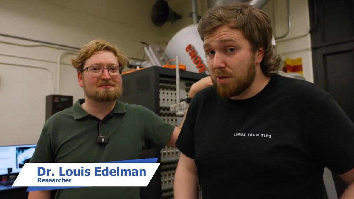
So Linus Tech Tips visited NASA's Langley Research Center to find out the minimum distance required for a PC's cooling fan to perform optimally.

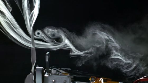
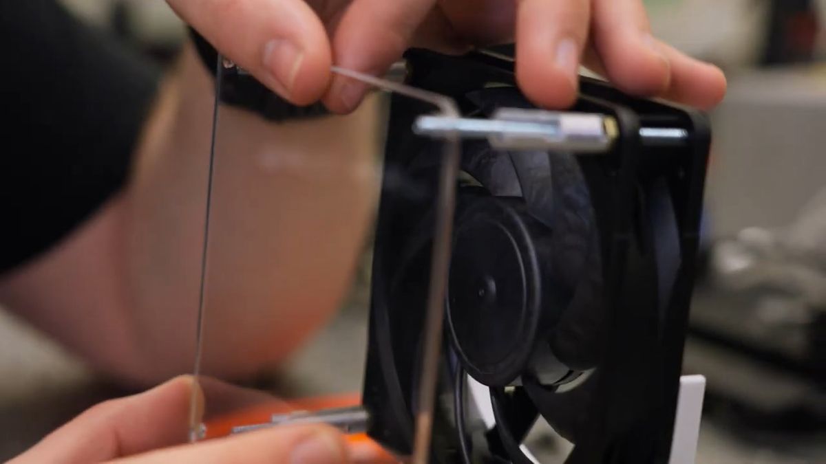
The materials we will be using for this experiment are this tape and string.
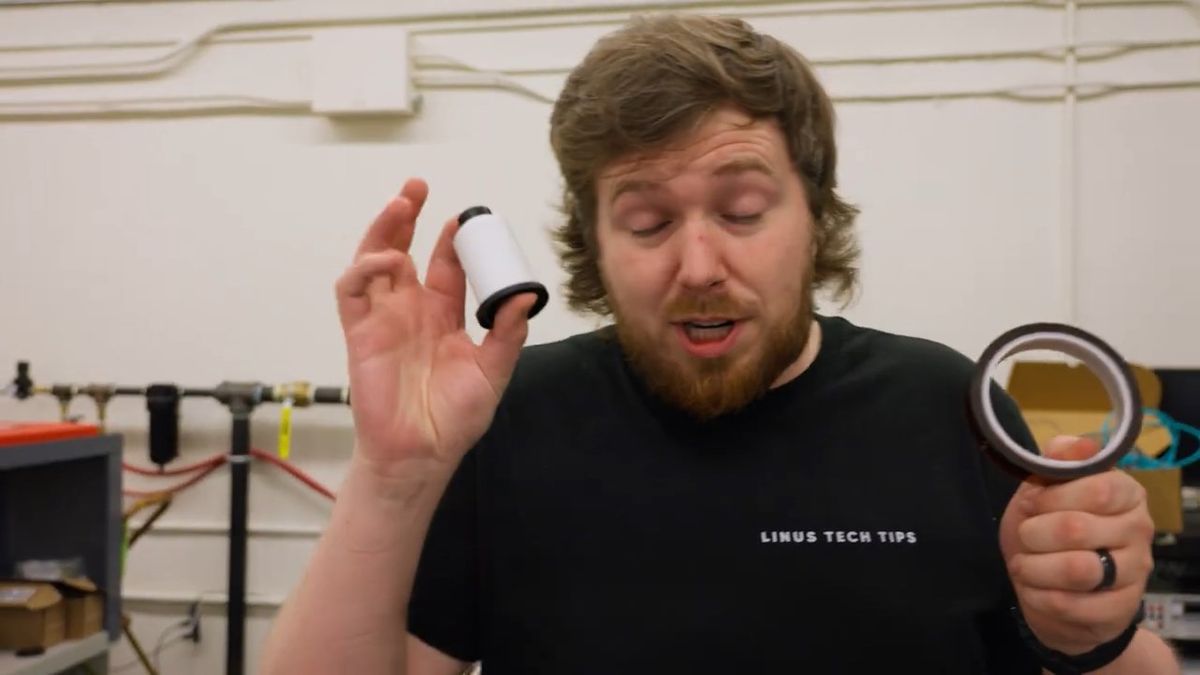
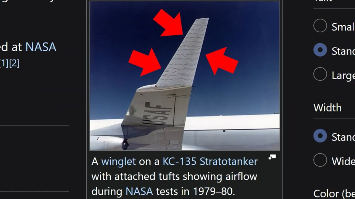
You might think this experiment is far too low-tech to be conducted at a NASA research facility, but this string-based experimental method is called ' Tuft' and is used in the field of aerodynamics to visualize airflow.
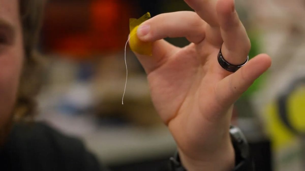
Tufting is an experimental technique that investigates airflow by observing how a string attached to an aircraft wing or other part of the aircraft moves.
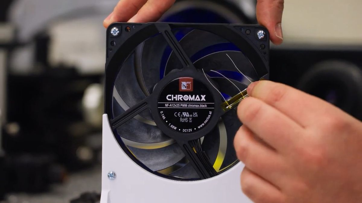
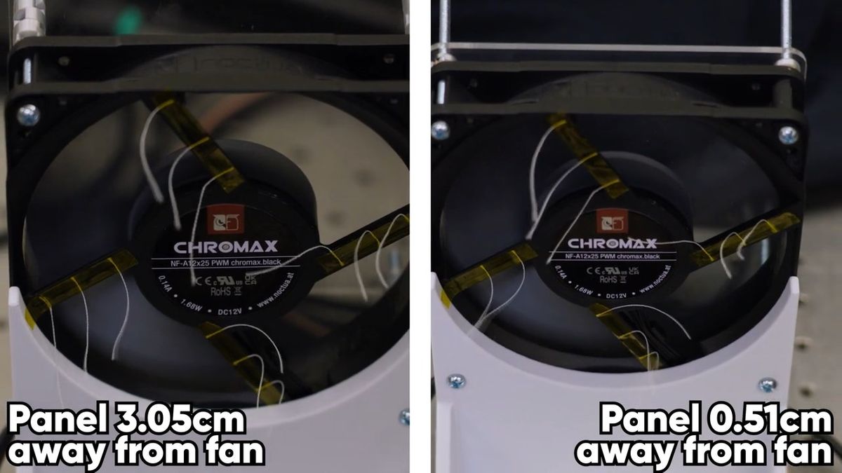
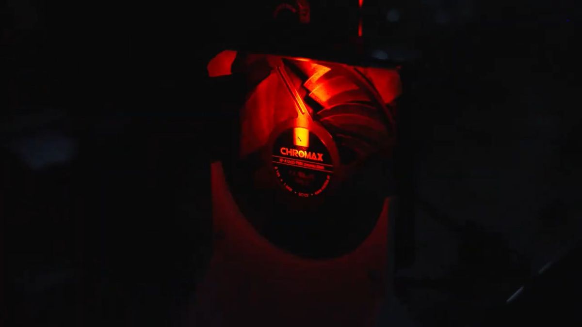
In the experiment, we placed an acrylic panel as an obstacle in front of a 120mm fan, a '
The tuft on the back looks like this.
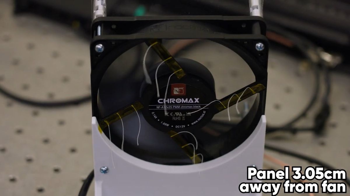
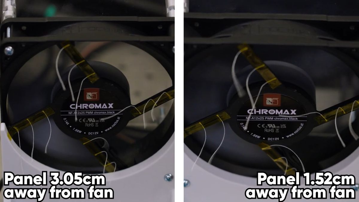
With the acrylic panel positioned at a sufficient distance of 3.05 cm from the fan, air flowed freely behind the fan. This indicates that the fan was able to properly draw in air from outside the case and cool the devices inside.
However, when the distance between the acrylic panel and the fan approached 1.5 to 2 cm, the string near the center began to loosen slightly.
Furthermore, when the distance between the acrylic panel and the fan was reduced to just 0.51 cm, it was found that not only did the airflow weaken considerably, but some of the strings were being sucked towards the fan. This indicates that the airflow inside the case is reversed and circulating.
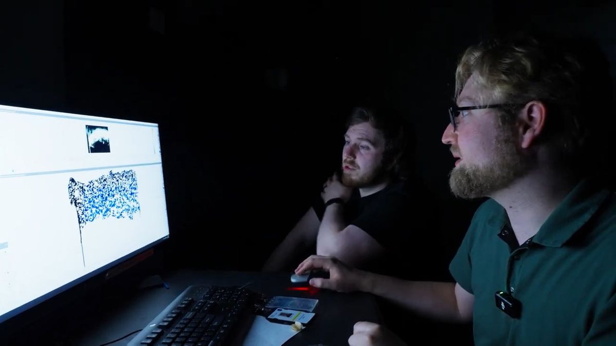
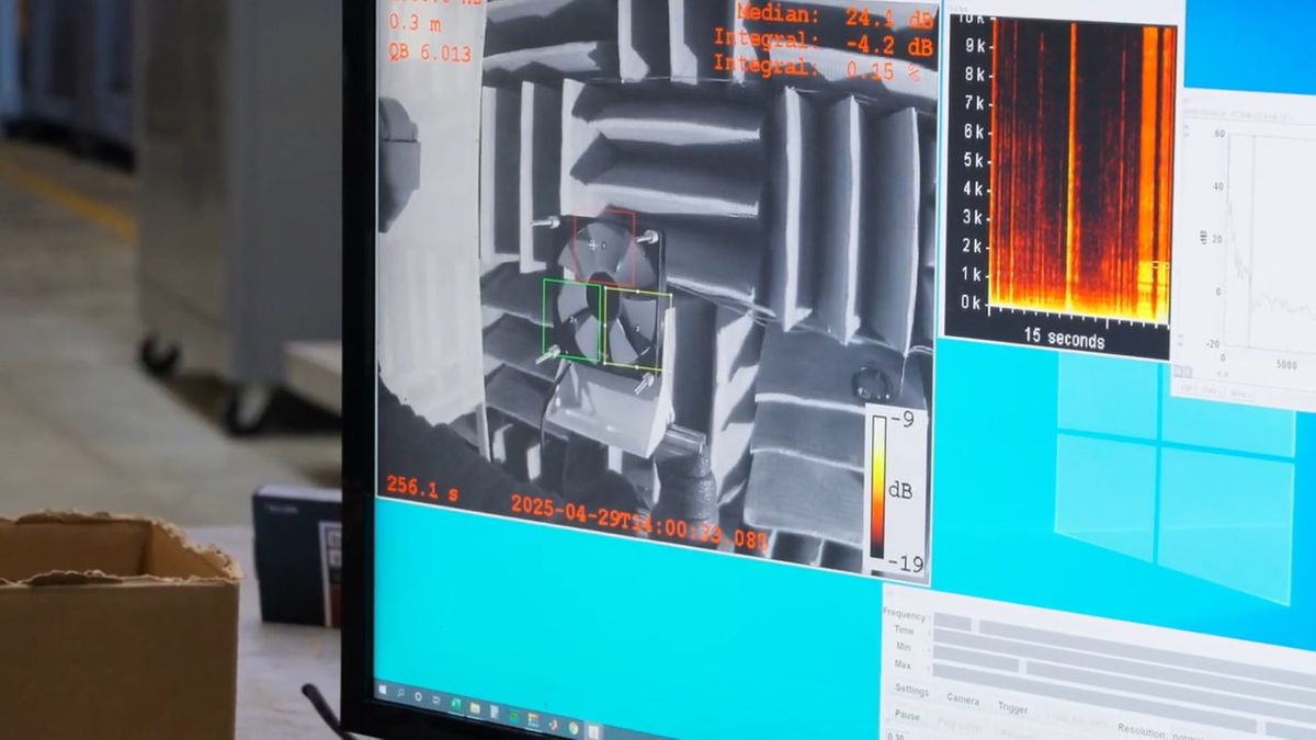
Next, Linus Tech Tips conducted an experiment called '
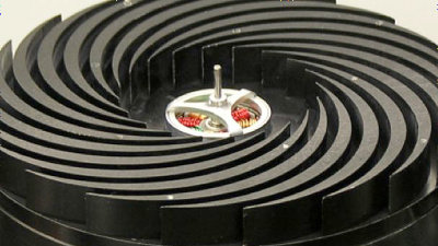
A high-performance camera used in PIV.
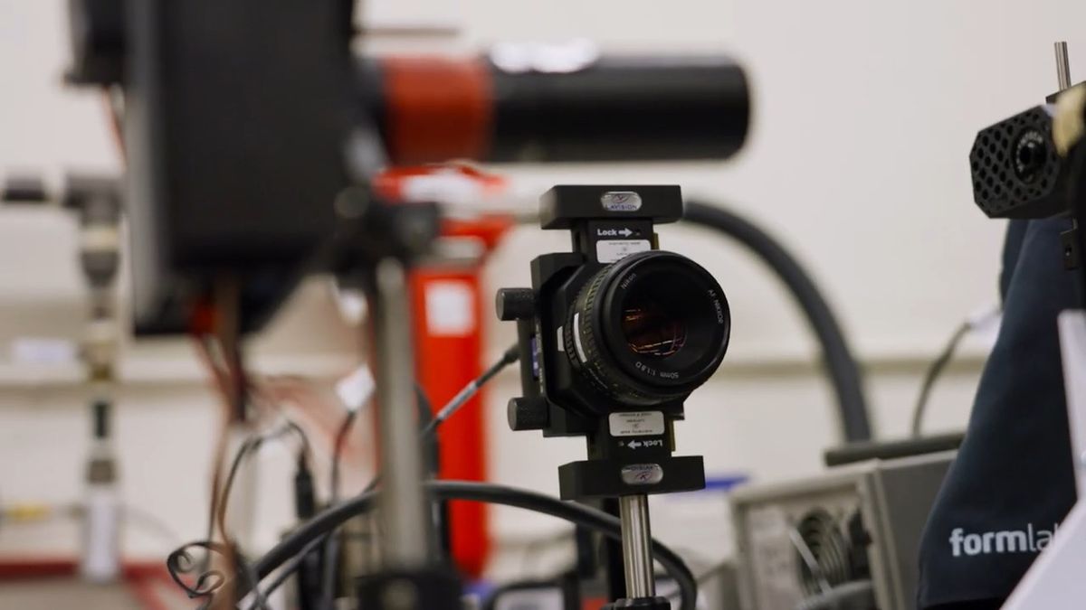
PIV repeatedly captures images of two samples at microsecond intervals, analyzing how particles moved between the first and second images to determine the direction and speed of their movement.

This is what the experiment looked like.
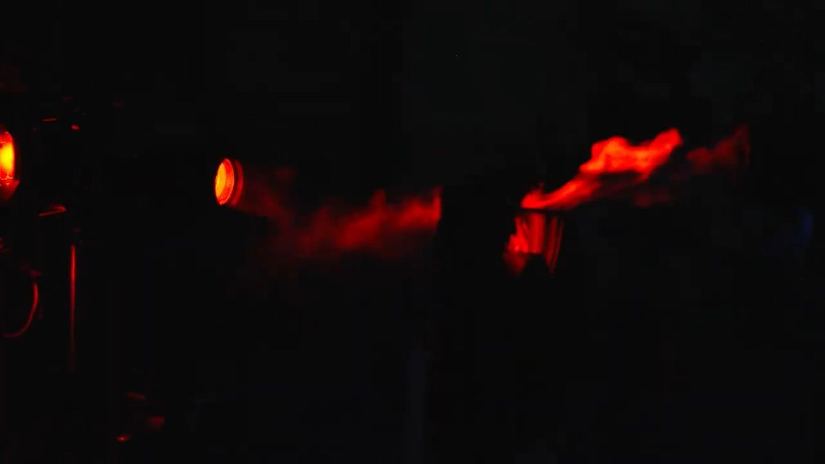
Fans are repeatedly taking pictures.
In this experiment, we took photos under four conditions: 'no obstruction in front of the fan,' 'a panel 2.2 cm away from the fan,' 'a panel 1.5 cm away from the fan,' and 'a panel 0.5 cm away from the fan,' and then analyzed the images using software.
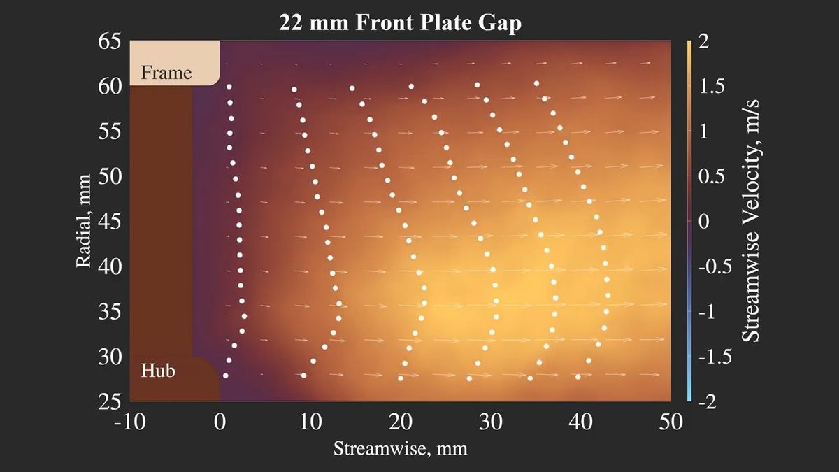
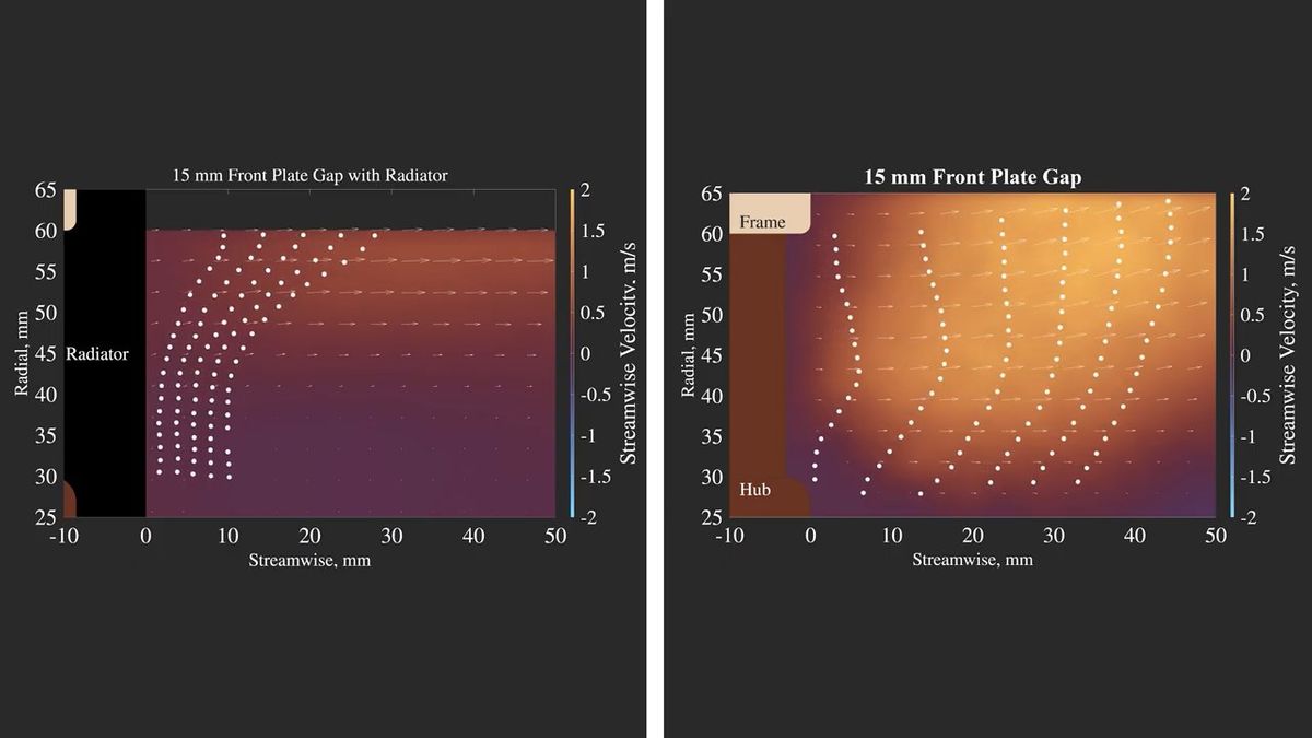
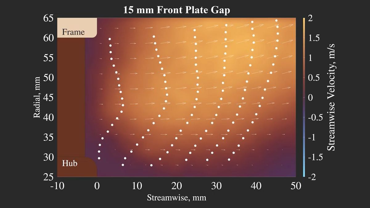
The following diagram illustrates the airflow from the center to the top of the fan in a scenario with no obstructions in front of the fan. The 'Hub' in the lower left refers to the center of the fan, and the 'Frame' in the upper left refers to the outer edge of the fan; the closer to the Frame, the closer to the outside of the rotating blades. The arrows indicate the direction of the airflow; the darker the color (closer to purple), the slower the airflow, and the closer to yellow, the faster the airflow. When there are no obstructions in front of the fan, it can be seen that the air flows smoothly towards the inside of the case.
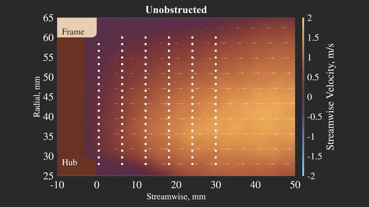
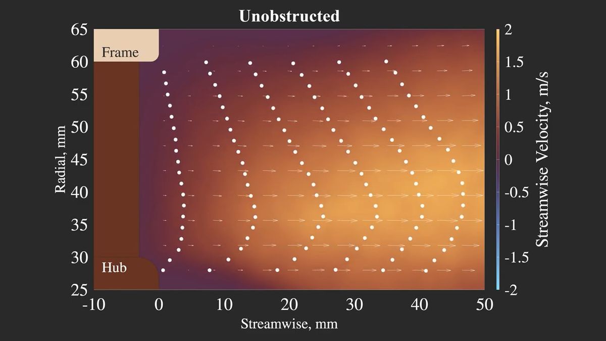
Here's what the particle movement looks like. The lower part of the diagram appears to have no airflow, but this is the center of the fan and therefore doesn't have blades, so it's not a problem.
It should be noted that this test only captured a two-dimensional airflow, but it was deemed to be sufficient for the purpose of understanding the performance of the cooling fan.
Next, let's look at the pattern where the panel is located 2.2 cm from the fan. The airflow still appears to be smooth.
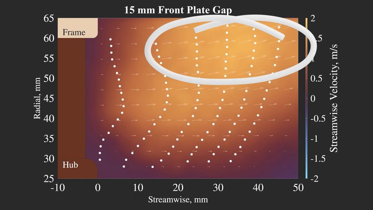
Next, looking at the pattern where the panel is located 1.5 cm from the fan, we can observe that the airflow is slightly directed outwards, while conversely, the airflow is weaker closer to the center. However, overall, the air is flowing well, and it seems that this level of restriction is unlikely to cause any major problems.
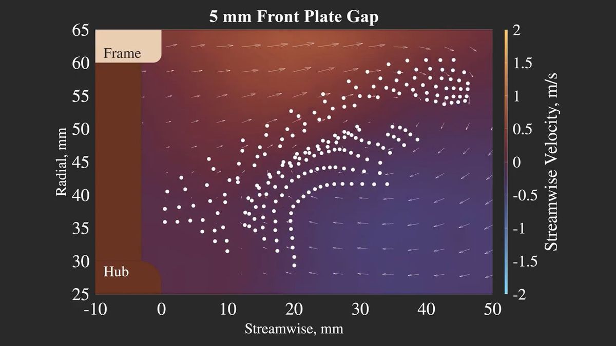
Finally, looking at the 'pattern where the panel is 0.5cm away from the fan,' it's clear that the airflow is stagnant. There's also airflow returning from inside the case towards the fan, so it seems that the cooling capacity is hardly being utilized.
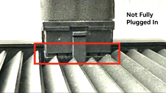
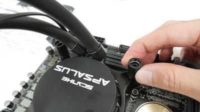
Next, we tested it with
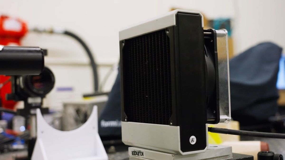
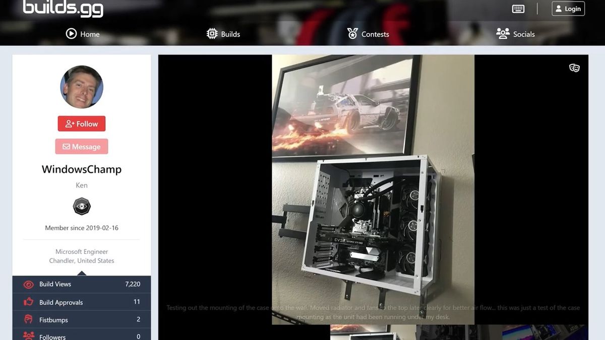
This is what it looks like when you place a panel 0.5cm away from the fan and then put the radiator on top. There's almost no airflow inside the case.
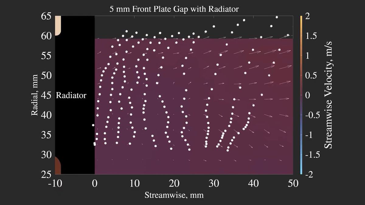
If you place a panel 1.5 cm away from the fan and then cover it with a radiator, the airflow will be as shown in the left diagram. It's better than when it's 0.5 cm away, but it's clear that the airflow is significantly weaker compared to the case without a radiator on the right.
Linus Tech Tips concluded that, at least when running the Noctua NF-A12X25 at maximum speed, it performs adequately even with a distance of about 1.5 cm between the fan and obstacles, but anything closer than that will seriously negatively impact its cooling capacity.

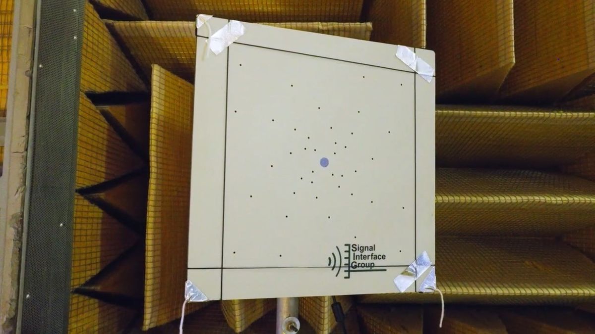
Furthermore, Linus Tech Tips also uses the acoustic facilities at the Langley Laboratory to test fan noise.
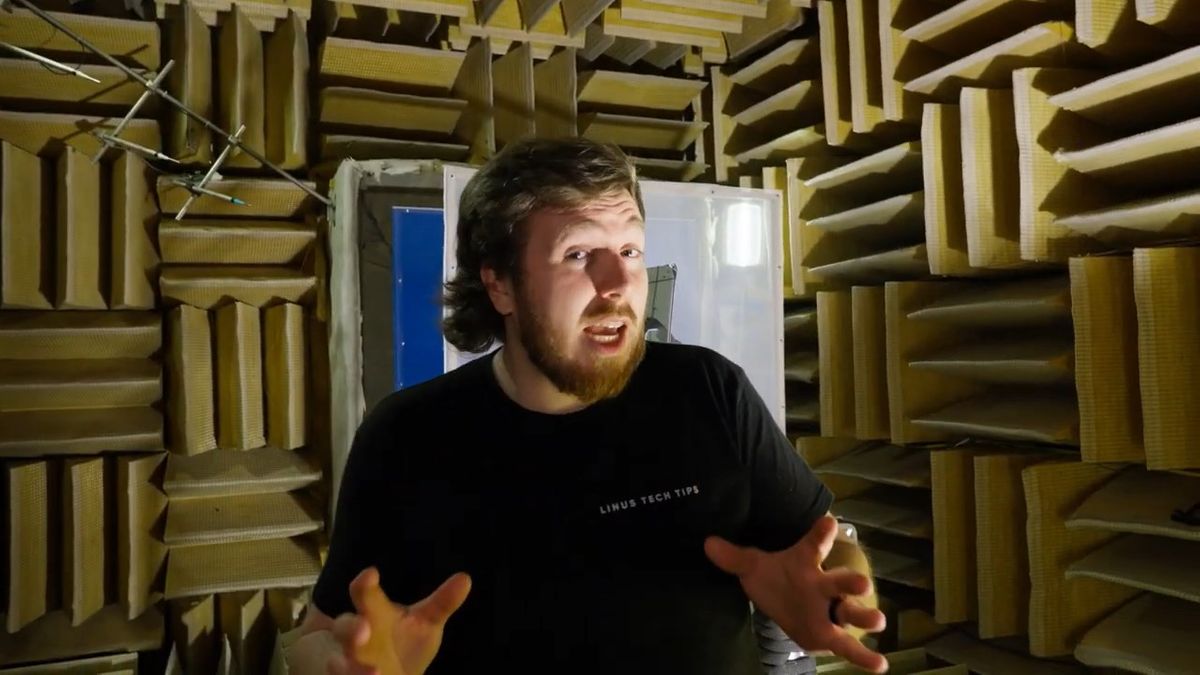
Through analysis using a very high-performance microphone and software, we can obtain extremely detailed information about sound.
Due to time constraints, they only tested two scenarios: 'a pattern with no obstacles in front of the fan' and 'a pattern with a panel 1.5 cm away from the fan.'
The graph below shows the results. The vertical axis represents the noise level (dB), and the horizontal axis represents the frequency range of the noise (Hz). Blue represents the pattern where the panel is 1.5 cm away from the fan, and red represents the pattern where there are no obstacles in front of the fan. It can be seen that a larger peak in noise is generated when the panel is placed at a distance of 1.5 cm.
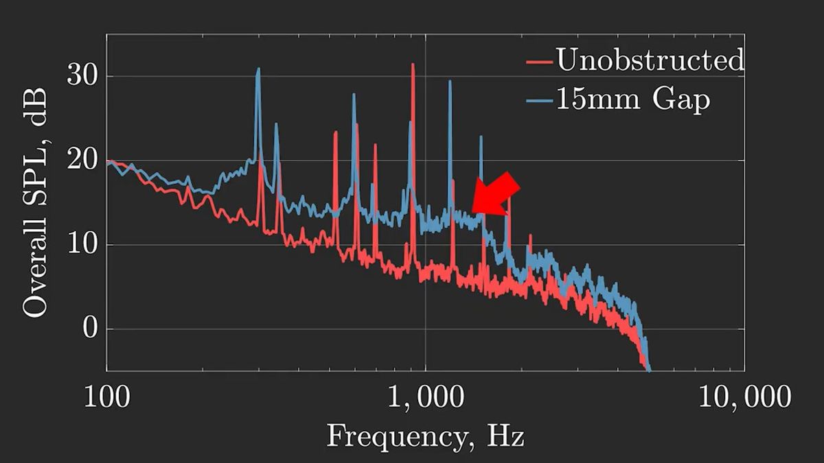
Linus Tech Tips explains that in cases where a panel is located 1.5 cm from the fan, the panel disrupts the overall airflow, resulting in increased noise. In other words, obstacles around the cooling fan not only worsen airflow but also increase noise.
Linus Tech Tips stated, 'For performance, keep the fan at least 1.5 cm away from any surface, and at least 2 cm away if there are other obstacles such as heatsinks or radiators. Regarding noise, it seems that being too far away from the fan is not a problem, but being too close can be a problem.'

Related Posts: