'Physically based rendering from first principles' that clearly explains the basics of 'light' in physically based rendering
To express realistic textures in CG, it is essential to simulate the interaction between light and objects using
Physically based rendering from first principles
https://imadr.me/pbr/
◆Chapter 1: What is light?
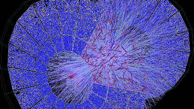
There was a mystery in that assuming either light is a wave or a particle would result in contradictory phenomena, but today quantum electrodynamics is recognized as the most accurate theory describing all interactions between light and matter. On the site, you can hover your mouse over each theory to find out which light phenomenon corresponds to which.
Physically based rendering uses
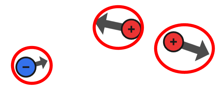
◆Electric force
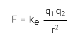
There are two types of electric charges: positive and negative. Charges of the same type repel each other, while opposite charges attract each other. The amount of force acting on two charged particles is calculated using Coulomb's law , where k is a constant, q1 and q2 are the amounts of each charge, and r is the distance between them.
On the site, you can actually move an electric charge and understand how the electric force affects it by looking at the direction and size of the arrows.
The image of
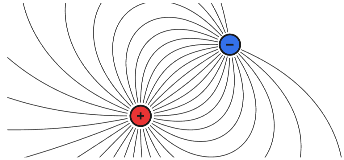
The image is animated, showing the electric field as a color gradient.

Special theory of relativity and magnetism
The site allows you to understand through animations the movement of charges as seen by an observer and the positive charge itself, and the force that acts on charges according to

◆Maxwell's equations
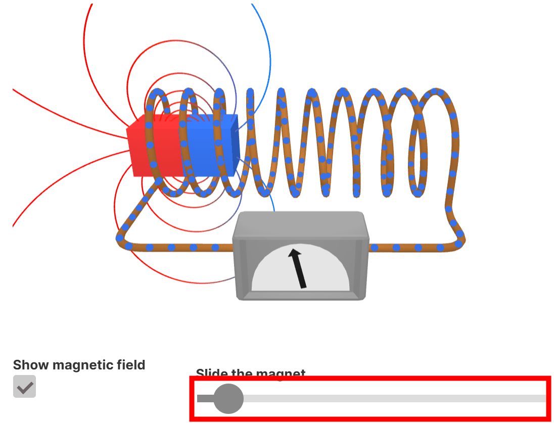
According to

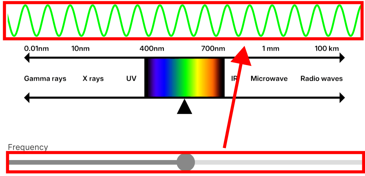
Electromagnetic waves
Waves generated by synchronized electric and magnetic fields are called
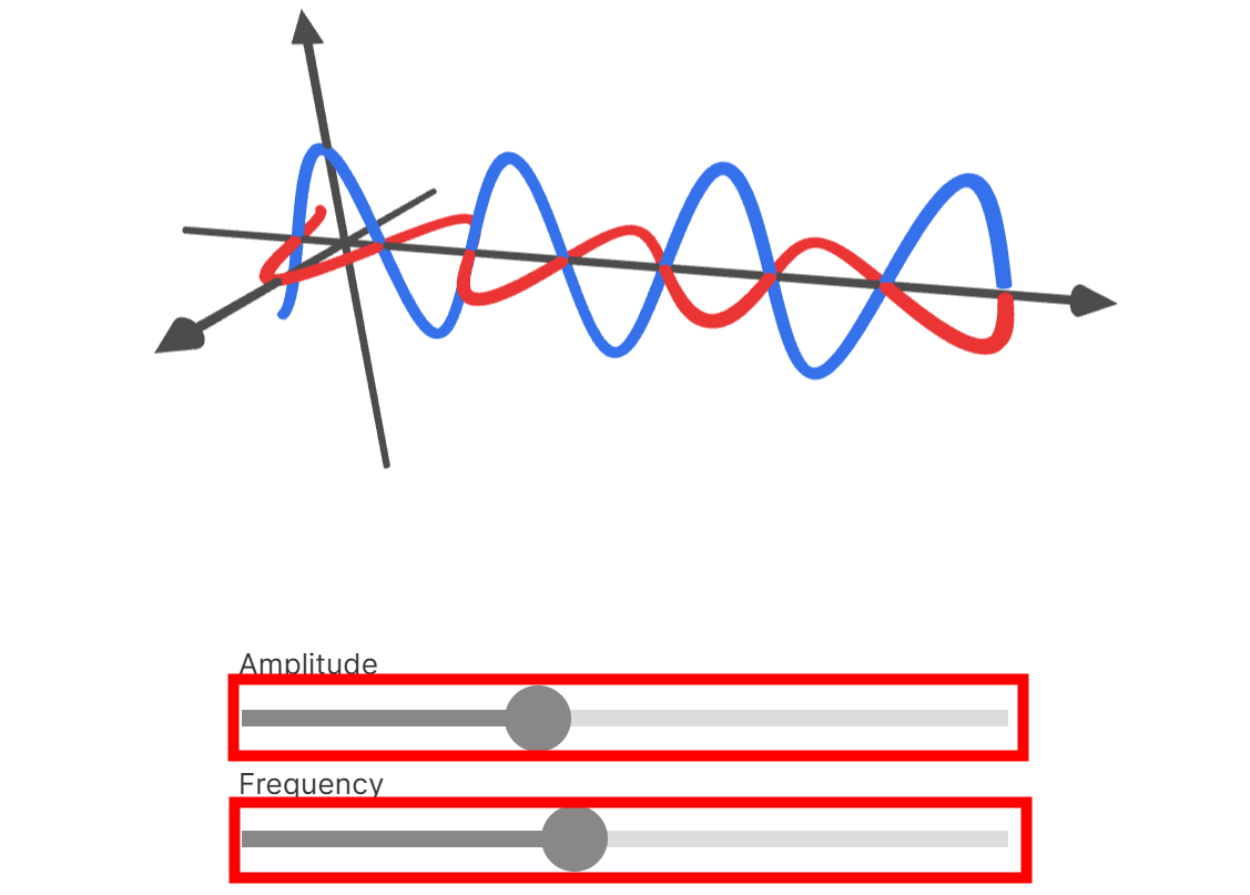
When the wavelength is between approximately 400nm and 700nm, the human eye perceives it as visible light. Moving the bar changes the frequency and color of the electromagnetic waves.
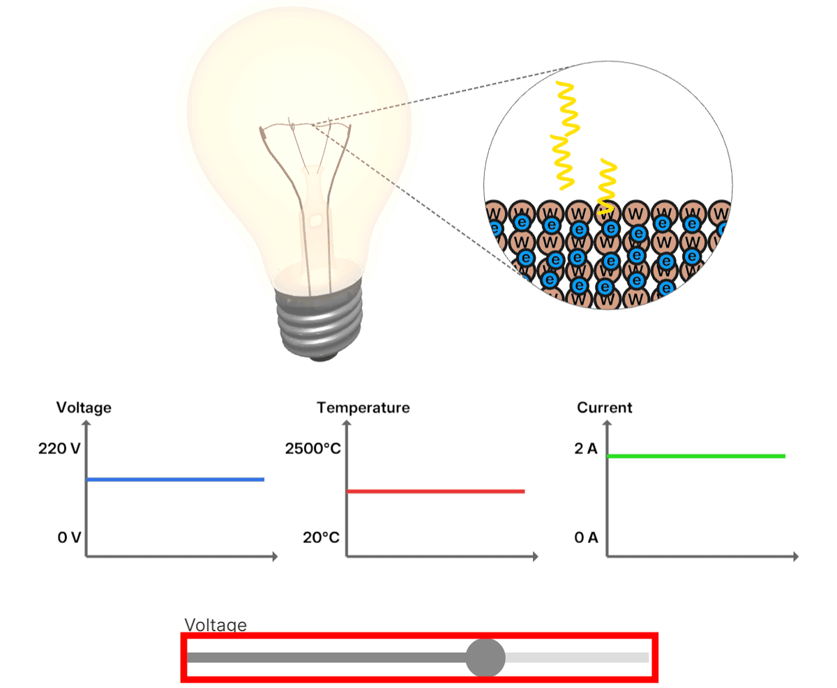
Light Generation
When an electric current is passed through an incandescent light bulb, the resistance of the filament generates heat, and as the electrons in the filament vibrate and collide, they emit photons. This light radiation is classified as
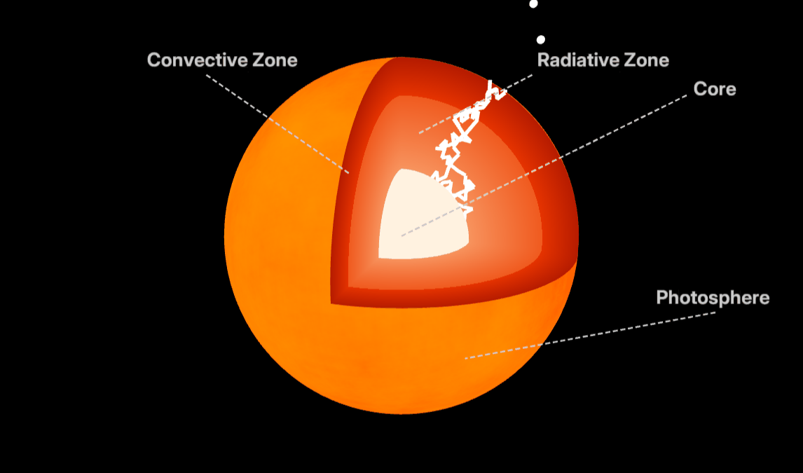
Unlike incandescent bulbs, the light emitted from the sun is produced by
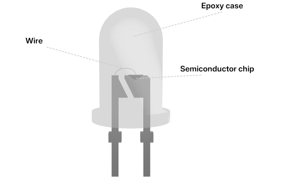
In an LED, when
Other light sources are listed in the Wiki's
◆Chapter 2: Abstraction of Light
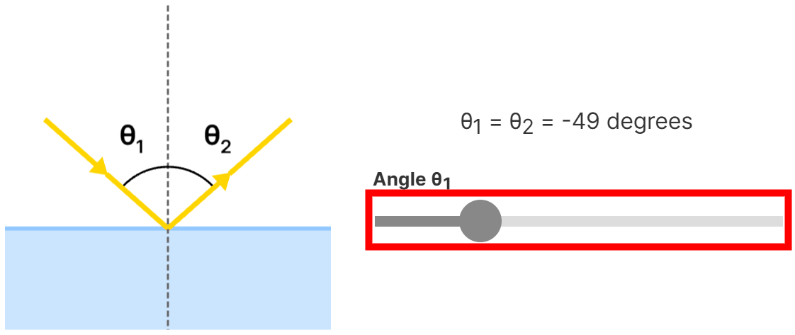
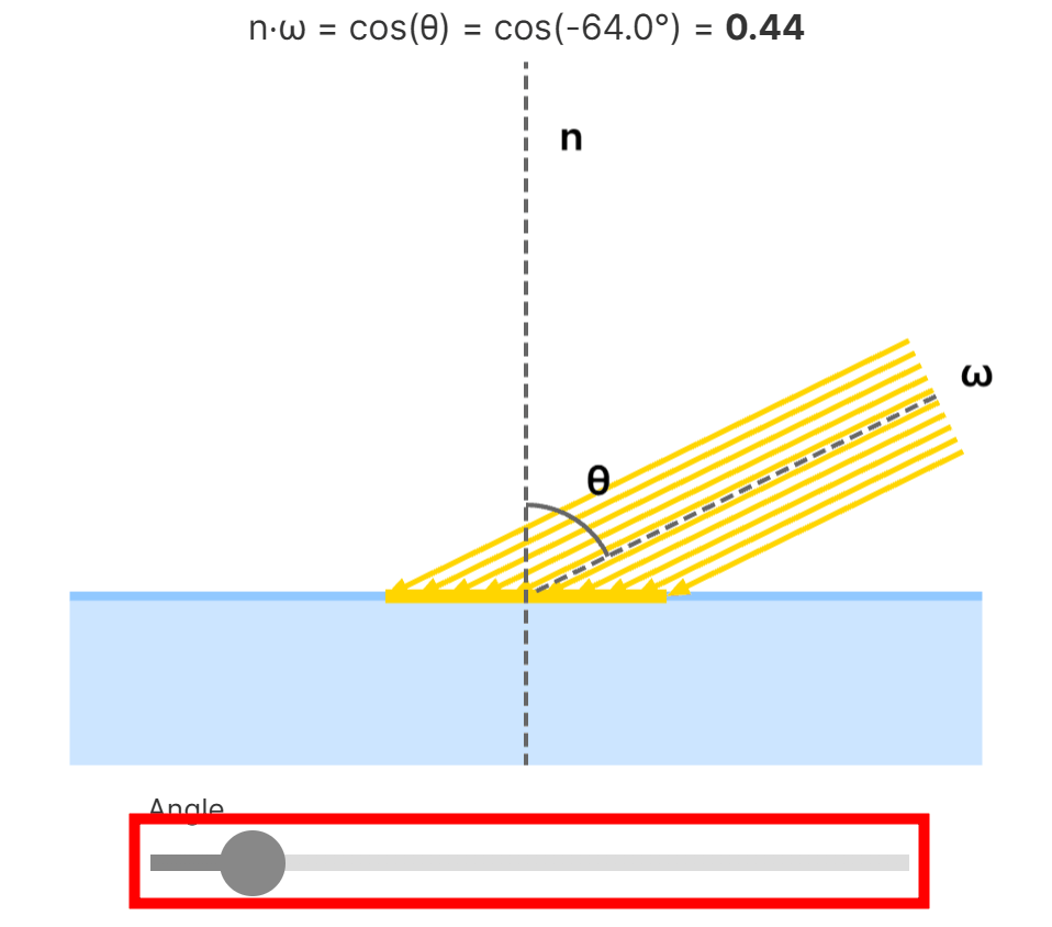
When a photon hits an object, it will either be reflected or refracted. According to the law of reflection, the angle of reflection is equal to the angle of incidence relative to the surface normal. Moving the bar will change the angle of reflection according to the angle of incidence.
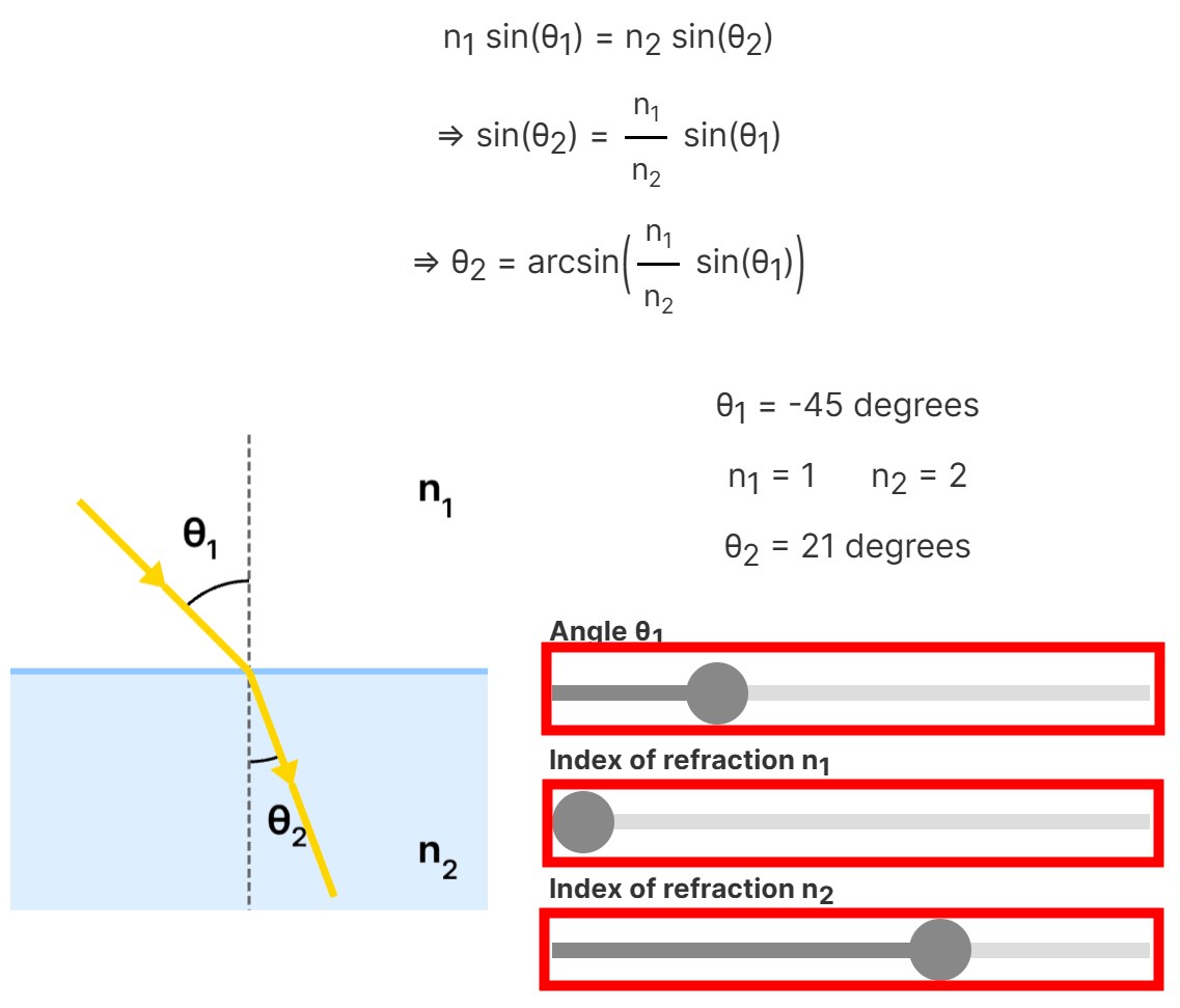
The refraction angle is calculated from
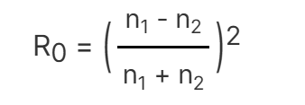
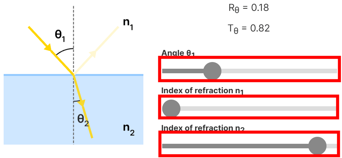
The amount of reflected and refracted light is determined by
First, calculate the reflectance at 0 degrees from the normal.
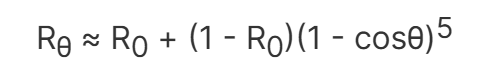
Next, substitute R0 into the approximate reflectance function.
The magnitude of transmitted light Tθ can be calculated from the magnitude of reflected light Rθ using the formula 'Tθ = 1 - Rθ.' By changing the angle of incidence θ1 of light and the refractive indexes n1 and n2 using the bar, the magnitude of reflected light and the magnitude of transmitted light can be calculated and reflected in the diagram.
The phenomenon in which all light is reflected is called
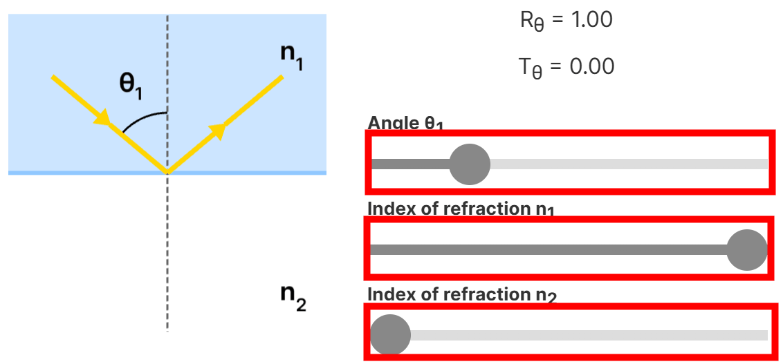
Total internal reflection causes a phenomenon known as
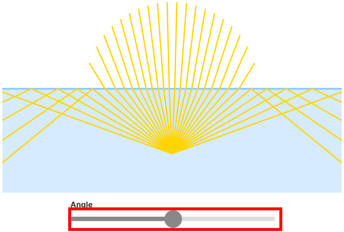
If you dive underwater and look up, the light on the surface will be refracted through a 96-degree wide circular window, creating the appearance shown here.

◆Microfacet model
For nanogeometry, on the scale of billionths of a meter,
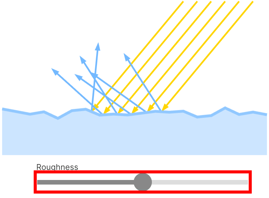
Computer graphics rendering goes even further, down to the pixel, treating each pixel as a microfaceted model containing millions of tiny microscopic surface irregularities, and using statistical averages to simulate the appearance of the surface at that pixel.
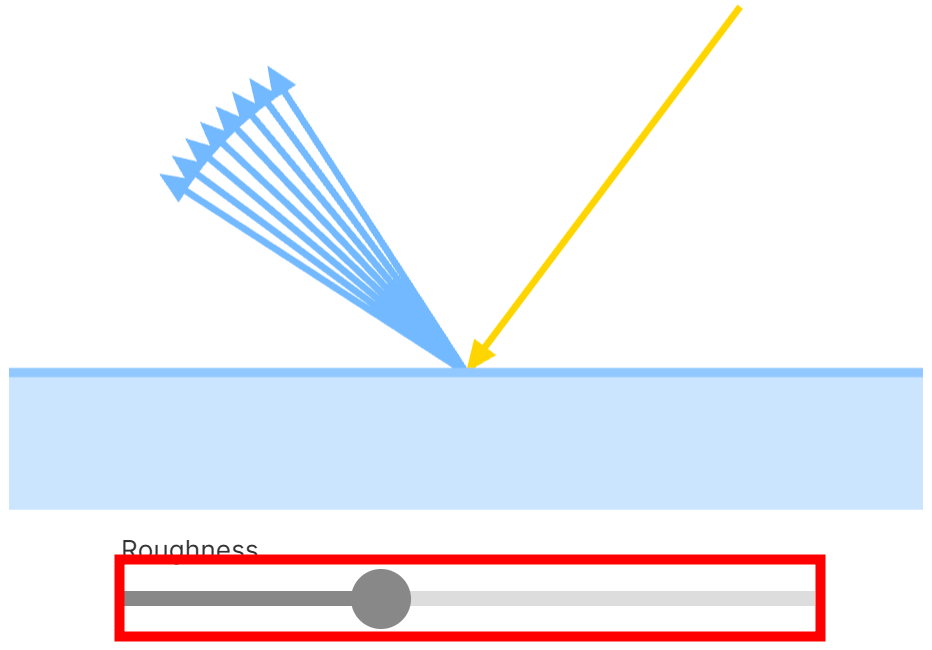
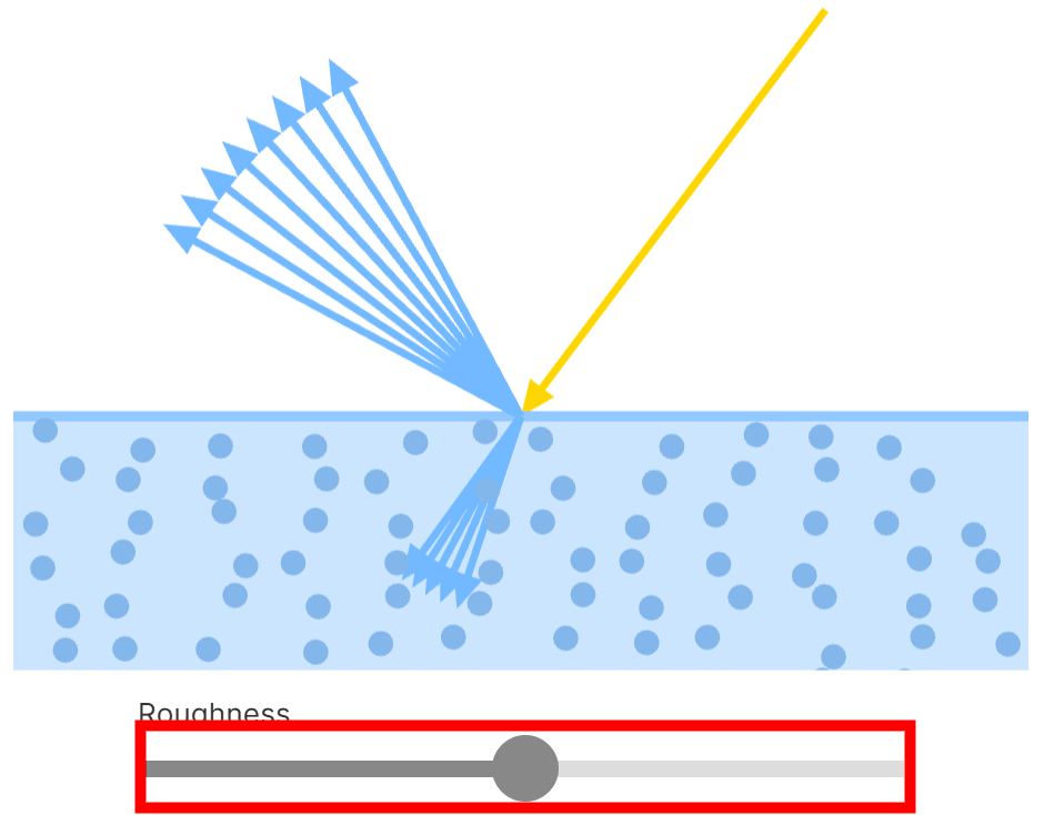
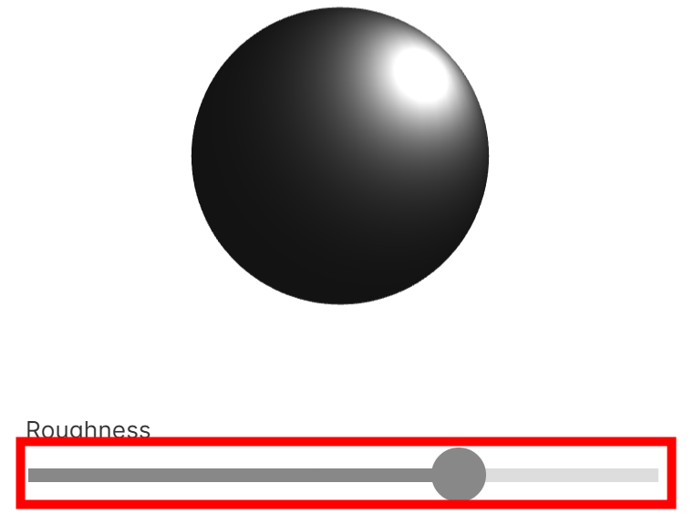
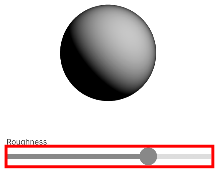
The normals of the microfacet model become less aligned as the surface becomes rougher. By moving the bar, you can change the surface roughness, and you can see how the direction of light reflection becomes more distorted as the surface becomes rougher.
Furthermore, the rougher the surface, the more the light rays spread out over a cone, and the size of this cone can be calculated using
Here, we distinguish between two types of microfacet models: metallic and non-metallic.
◆Metal
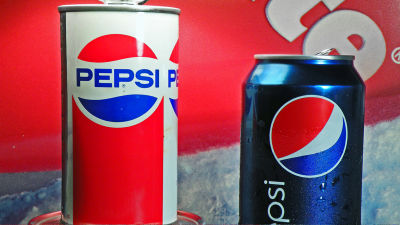
In metals, photons are easily absorbed by free electrons within a few nanometers of the surface. Unabsorbed light is reflected evenly across the visible light spectrum, producing a distinctive silvery-gray color. The exceptions are gold, copper,
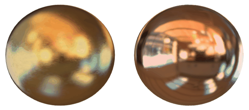
Changing the roughness of the metal surface changes the specular reflection, but diffuse reflection does not occur because photons other than the reflected light are absorbed.You can see that when you move the bar to change the surface roughness, the specular reflection changes but diffuse reflection does not occur.
◆Nonmetal
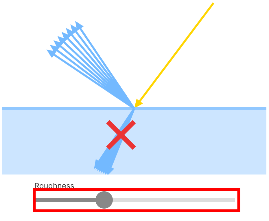
Non-metals include materials that do not conduct electricity, called
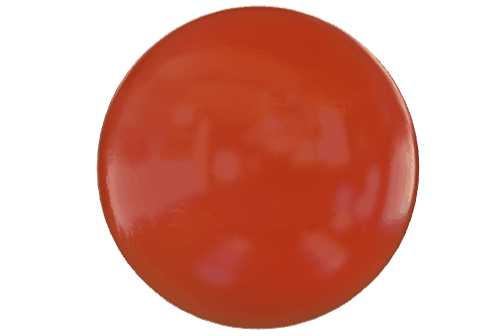
When a photon hits a dielectric material, it is only absorbed if its energy matches the energy of an electron in the object; if it does not, specular reflection occurs. A further phenomenon called diffuse reflection occurs, where light refracts within the dielectric material, interacting with pigments in the material and bouncing around before exiting the surface. Surface roughness affects specular and diffuse reflection. By moving the bar to change the surface roughness, you can see how specular and diffuse reflection change.
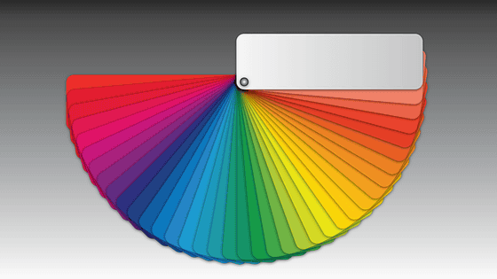
◆Spectral distribution
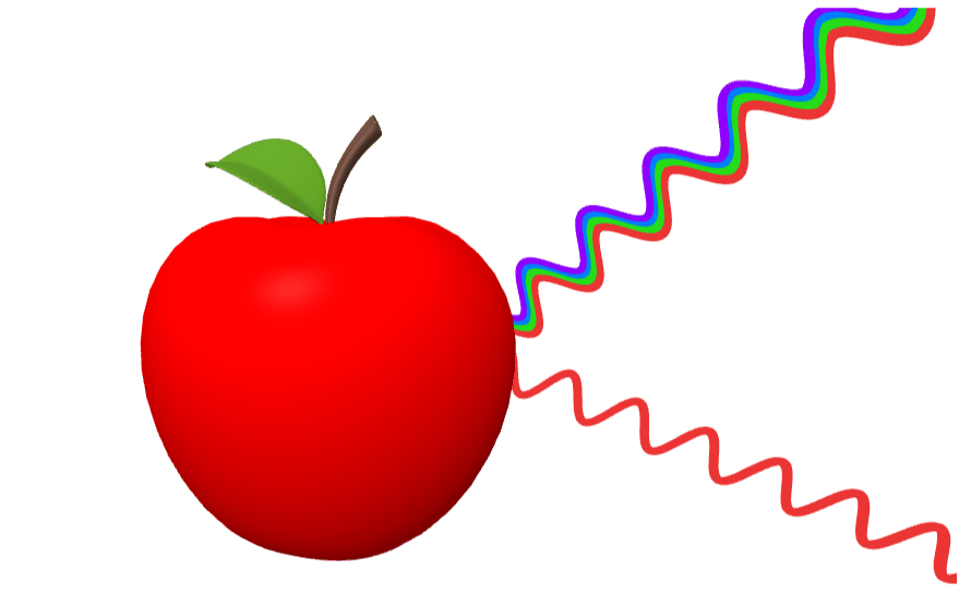
When a red apple is illuminated with white light containing all visible wavelengths,
The amount of energy carried at each wavelength in incident light can be graphed using a function called
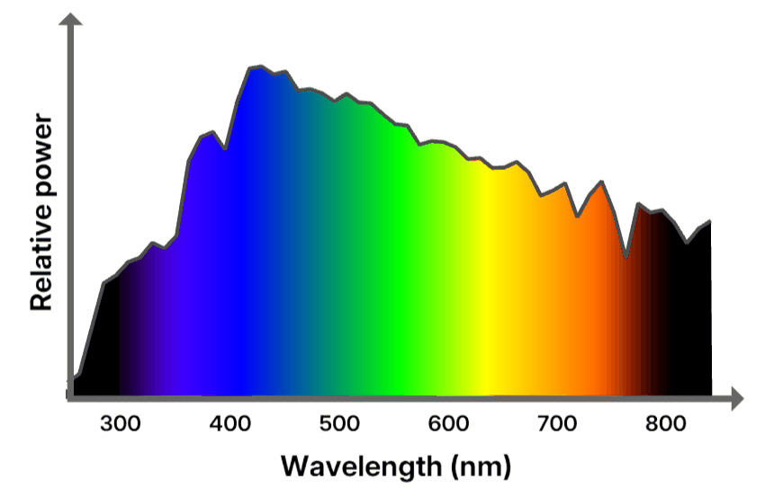
Comparing with the SPD of solar radiation
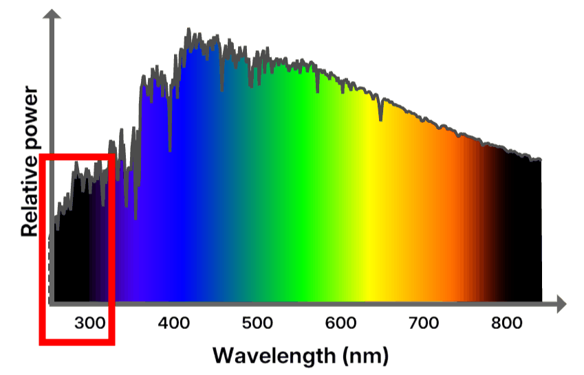
The SPD for a tungsten incandescent lamp is as follows:

◆Spectral reflectance curve
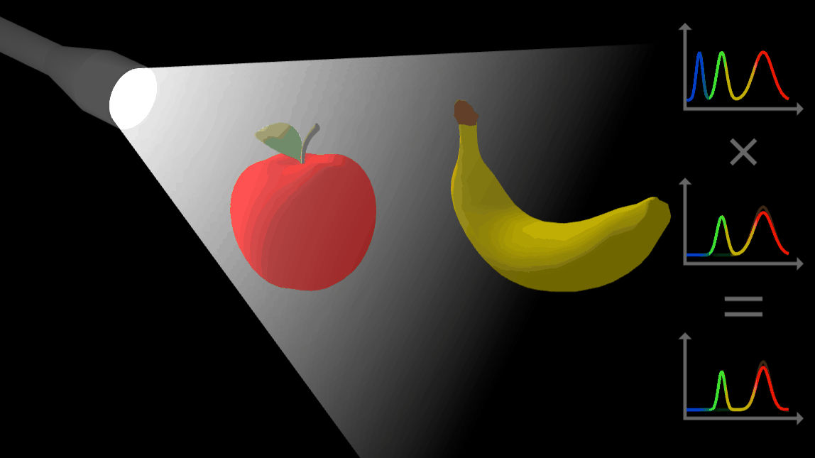
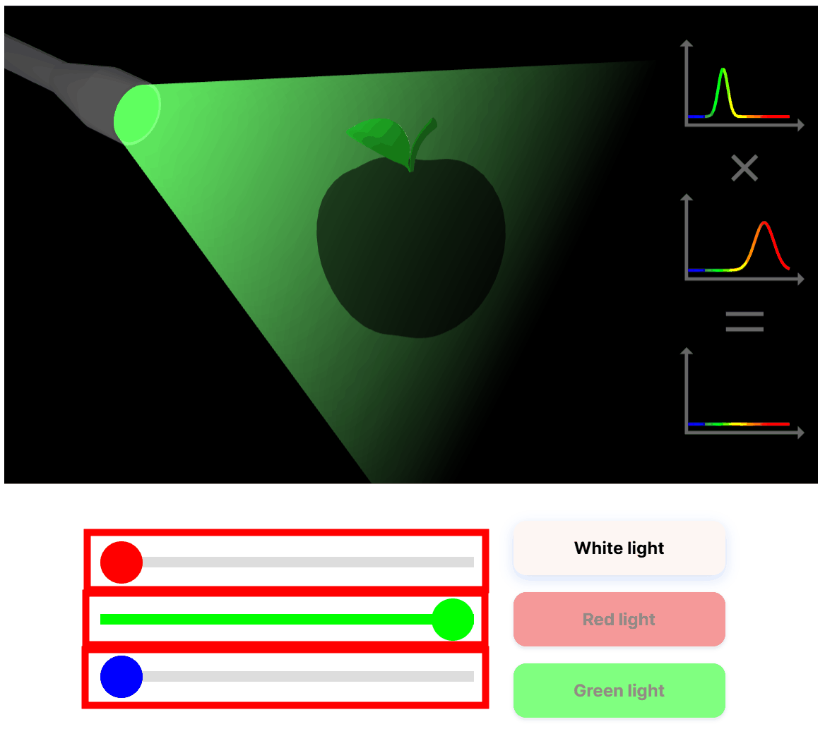
SPD tells us how much color a light source is made up of, while

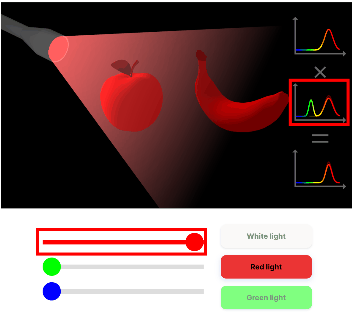
The color of an object appears to be the result of a combination of the spectral distribution of the light source and the object's spectral reflectance. If you shine white light on a red apple, the apple will appear red, and the same result can be achieved with red light. However, if you shine green light on it, the rest of the apple, except for the leaves, will not reflect light and will appear black. The site has bars that allow you to adjust the intensity of the red, green, and blue light emitted by the flashlight, and you can see how the red apple will appear according to the SPD.
The reason why a banana appears yellow under white light is because yellow is the composite color obtained by reflecting green and red. When illuminated with only red light, the banana only reflects red, so it appears reddish. This phenomenon, in which a red apple and a yellow banana appear the same red under red light, is called
◆Chapter 3: Rendering Equations
An example of a rendering equation used in physically based rendering.
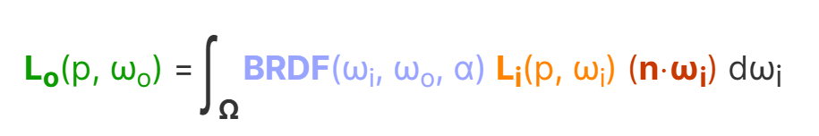
・Lo(p,ωo): Light emitted from point p in the direction ωo
・Li(p,ωi): Incident light from direction ωi to point p
Bidirectional reflectance distribution function (BRDF): A function that indicates how much of the incident light Li(p,ωi) is reflected at point p in the outgoing direction ωo, and indicates the material.
・Dot product: cosine term
The rendering equation derives the outgoing light Lo reflected at point p towards direction ωo by summing all incoming light Li coming from directions ωi in the hemisphere Ω, weighted by the BRDF at that point and a cosine term.
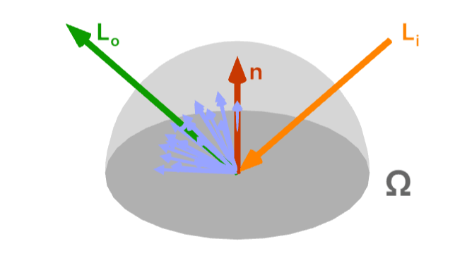
We will explain this rendering equation item by item.
◆Lambert's cosine law
According to
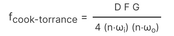
◆Bidirectional reflectance distribution function (BRDF)
The BRDF is the most important part of the rendering equation, it describes the surface of a material and its appearance. Here, microfacet theory and energy conservation can be applied to make the rendering model physically based. It represents the incoming light direction ωi and the outgoing light direction ωo, the surface roughness α, and the diffuse and specular reflection components weighted by the coefficients kd and ks respectively.

There are many types of BRDFs, but the most common for real-time rendering is
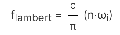
The Lambertian diffuse component is the diffuse color called
◆Normal distribution function
The normal distribution function is a function that approximately represents the number of tiny planes oriented to reflect light that is reflected from the incident direction ωi toward the outgoing direction ωo. In this example, we will use the Trowbridge-Reitz GGX function.
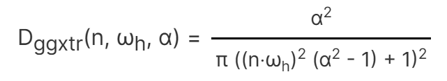
ωh is the half vector between the incident and outgoing directions, and is given by:
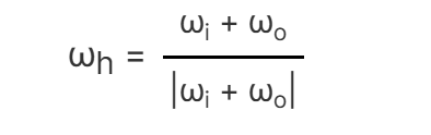
On the site, you can see how the surface roughness and number of microfacets change as the bar is moved.
◆ Geometric functions
In the diagram below, the red incident light ray is in a state called shadowing, where it cannot bounce back in the direction of emission. The blue incident light ray is blocked on its way to the emission direction, a state called masking. Moving the bar changes the angle of the incident light ray, resulting in changes to the red shadowing light and blue masking light.

These effects are approximated by geometric functions, here we use the Schlick-GGX geometric functions.

The value of k is as follows:
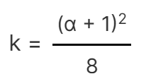
Moving the bar changes the surface roughness, which changes the shadowing and masking effect.
Fresnel equation
For real-time rendering, we use Schlick's approximation, which is fast and sufficiently accurate.
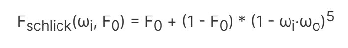
By moving the bar, the reflectivity changes and you can see the change in the intensity of the reflected light.
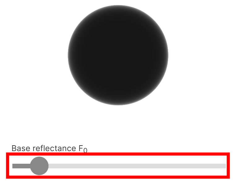
◆ Putting it all together
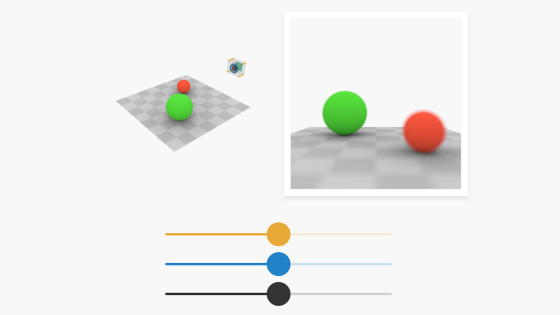
These formulas are combined to produce physically based rendering, which the site allows users to visualize by changing the surface roughness, metalness value, and base color on the bars.
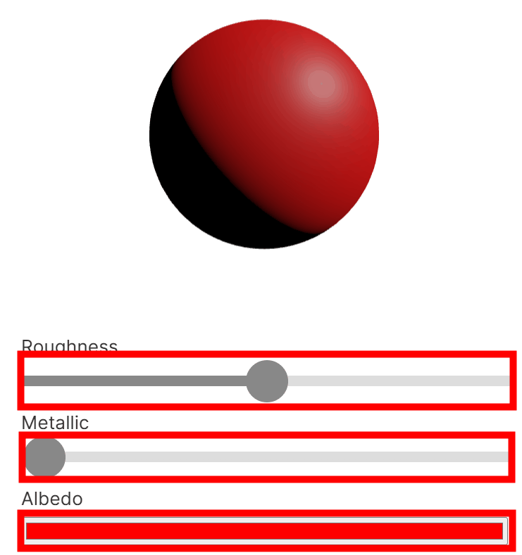
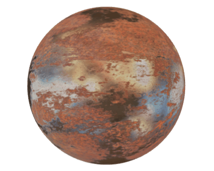
Here is a table showing the correlation between the surface roughness of the sphere and the metallurgical value:
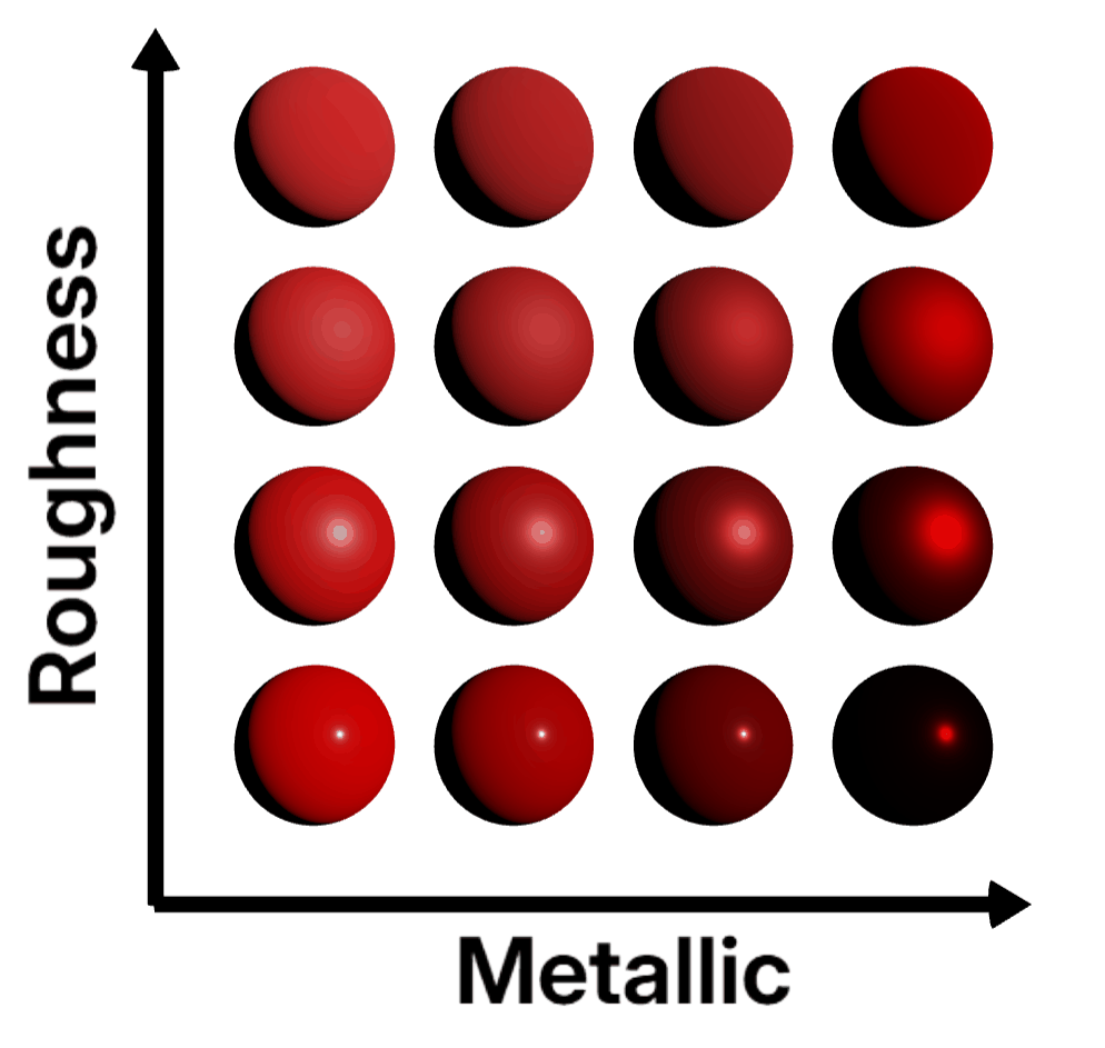
Typically, metal values are either 0 or 1, but in physically based rendering it is practical to allow for intermediate values, smoothly interpolating between metal and non-metal, which can be useful for representing rusted metal materials.
The explanations on the site cover the basics, and in the future they will cover effects such as volume rendering, subsurface scattering, optical dispersion, thin film interference, and rainbow colors.
Related Posts: